Leading the world in
energy absorption
The aircraft industry provided the first application for the Oleo gas hydraulic energy absorber principle in landing gear.
Over the last sixty years Oleo has developed and refined this to meet the specific needs of the rail industry. The units are made from precision parts, protected and sealed against contamination to reduce the need for maintenance even under arduous operating conditions to provide:
Controlled impact energy dissipation that improves passenger safety and minimises costly damage to rolling stock.
Virtually all of the impact energy is dissipated over the closure stroke avoiding damaging re-coil forces.
Uniform deceleration level in order to maintain minimum impact forces.
Accurate, predictable and consistently repeatable performance characteristics.
Long maintenance free service under normal operating conditions.
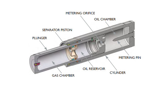
The illustration shows the robust construction of the Oleo hydraulic unit. Under impact the plunger is forced into the cylinder displacing oil through the orifice, moving the separator piston and compressing the gas. The compressed gas acts on the oil through the separator piston to give recoil force to re-extend the unit after impact. The energy absorbed and dissipated is dependent on the closure velocity.
When the plunger is forced into the cylinder rapidly, the oil displaced by the plunger has to pass through the orifice at very high velocity. This raises the pressure in the oil chamber to a level which optimises the closure force of the unit.
This optimisation process ensures that the impact energy is absorbed evenly throughout the plunger travel maintaining a level impact force. This very useful feature is accomplished by Oleo's innovative metering designs which progressively alter the flow area as the unit closes. The actual metering designs are precisely calculated to provide the best possible protection to rolling stock at specified impact speeds.
The Oleo hydraulic unit therefore possesses the unique feature that its characteristics change according to operational needs. The majority of the impact energy is absorbed within the unit and the already low recoil force is damped by the reverse flow of oil, leaving very little energy and recoil force to be returned to the impacting vehicle.
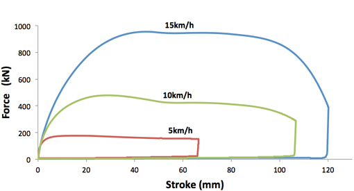
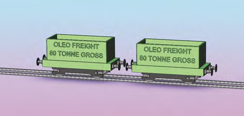
The graph below illustrates the energy absorption characteristics as speeds increase.
This shows the impact of two identical rail vehicles and illustrates how the whole stroke is used to absorb energy as speeds increase.
DYNAMIC CHARACTERISTICS
STATIC CHARACTERISTICS
When the plunger is moved slowly, oil passes through the orifice at a low velocity with little pressure drop, so that the resistance to closure is low and controlled mainly by the compression of the gas. This gives a "soft" or static characteristic to cushion low speed impacts gently.
The Oleo hydraulic energy absorber provides ultimate protection controlling the deceleration of rolling stock, whatever the speed of impact, keeping end forces down to a minimum and absorbing energy by conversion into heat. Recoil forces are also kept to a minimum and further damped by the reverse flow of the oil.
The key advantages are:
Long maintenance free service – for the lowest life cycle costs.
Highest efficiency – more than 95% of the impact energy is dissipated into heat.
Uniform energy absorption over the full stroke.
Controlled and predictable impact forces.
Hydraulic cushioning provided is fully reversible.
Low recoil forces.
Specialist plated working surfaces for smooth and wear resistant action.
Recoverable energy absorption methods commonly used in the rail industry are:
a) Oleo gas hydraulic buffers (with all the advantages outlined above).
b) Fluid elastomer
This generally consists of a pot of polymer based fluid, a plunger consisting of a rod and a larger diameter head which is pushed into the fluid when the buffer is stroked. The fluid material is very viscous and operates at high pressure at which the material is compressible. The slow closure characteristic is a function of the change of fluid volume when the plunger is pushed in the pot. The dynamic characteristic is a function of the fluid having to flow past the head when the plunger rapidly enters the pot.
Fluid elastomer buffers slow closure characteristic tend to be rather stiff and dynamically they only utilise their full stroke at higher impact velocities. Even when the fluid elastomer fully strokes they are not as efficient as hydraulic buffers. At lower speed impacts, which occur more frequently, they do not use their full stroke and therefore their efficiency is reduced further. Fluid elastomer energy absorption characteristics are velocity sensitive and dependent on the positioning of its long chain molecules and this, combined with material properties that vary from batch to batch, make their performance unpredictable and not suitable for numerical simulation.
c) Ring springs (or friction springs)
These consist of a series of concentric inner and outer rings designed in such a way that the inner rings compress and the outer rings expand when a tensile load is applied. The strain energy stored in the rings form the basic underlying spring characteristic. The friction generated when the inner and outer rings 'ride' over each other provide the spring with its energy absorbing characteristics. Ring springs have a linear force displacement characteristic and dissipate approximately 66% of the energy stored, the remaining 33% is returned to the impacting masses as kinetic energy. Their dynamic characteristics are very similar to the static characteristic. For any given stroke ring springs generally have less than half the capacity of hydraulic buffers.
d) Solid elastomer
A solid elastomeric spring consists of a series of thermal plastic 'donuts' separated by metallic shims. When compressed energy is stored within the material as strain energy. The energy is dissipated within the material during both the compression and extension of the material due to the internal friction rising from the long cross linked polymers within the material. Solid elastomer performance is similar to rubber buffers but with significantly better endurance and improved energy capacity. Solid elastomer buffers absorb approximately 50% of the stored energy, the remaining 50% is returned to the impacting masses as kinetic energy. The force displacement characteristic of a solid elastomer buffer is less than linear. Compared to hydraulic buffers the solid elastomer buffers have poor energy absorption and dissipation performance. For any given stroke solid elastomer buffers have less than half the capacity of hydraulic buffers.
e) Rubber
Rubber buffers come in many arrangements, but generally consist of a series of plates with rings of rubber bonded to the surface. When compressed energy is stored within the material as strain energy. The energy is dissipated within the material during both the compression and extension of the material due to the internal friction. Rubber buffers have similar poor energy absorption and dissipation performance as solid elastomer but with the additional disadvantage that they do not have the same life expectancy of the solid elastomer buffers.
All of the above are used in buffers, couplers and anti climbers. They all absorb impact energy with different degrees of efficiency and they all return different amounts of the absorbed energy during recoil.
The graph below shows the characteristics of the various energy absorbers at the maximum impact speed while keeping the end force below 1000kN to avoid the onset of structural damage to the rail vehicle.
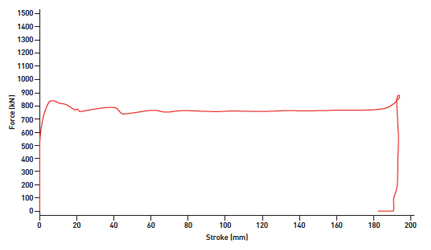
GAS-HYDRAULIC – FORCE v STROKE
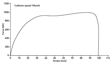
Oleo Gas-Hydraulic side buffer
Collision velocity of 15.0km/h
Energy stored (We) = 84.4kJ
Energy absorbed (Wa) = 84.3kJ
Maximum stroke = 98mm
Efficiency (We / Wa) = 99.9%
FLUID ELASTOMER – FORCE v STROKE
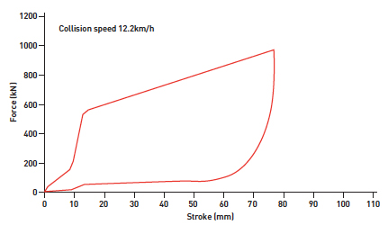
Typical Fluid-Elastomer side buffer
Collision velocity of 12.2km/h
Energy stored (We) = 52.9kJ
Energy absorbed (Wa) = 42.8kJ
Maximum stroke = 75mm
Efficiency (We / Wa) = 81%
RING SPRING – FORCE v STROKE
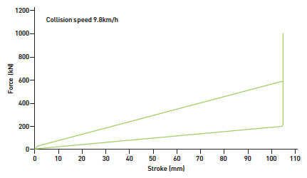
590kN Ring Spring side buffer
Collision velocity of 9.8km/h
Energy stored (We) = 32.0kJ
Energy absorbed (Wa) = 21.1kJ
Maximum stroke = 105mm
Efficiency (We / Wa) = 66%
ELASTOMER – FORCE v STROKE
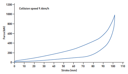
Simulation of Solid Elastomer side buffer
Collision velocity of 9.4km/h
Energy stored (We) = 29.0kJ
Energy absorbed (Wa) = 15.6kJ
Maximum stroke = 100mm
Efficiency (We / Wa) = 54%
RUBBER – FORCE v STROKE
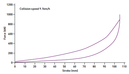
Category A Rubber side buffer
Collision velocity of 9.1km/h
Energy stored (We) = 27.0kJ
Energy absorbed (Wa) = 13.9kJ
Maximum stroke = 105mm
Efficiency (We / Wa) = 51%
COMPARING THE RELATIVE PERFORMANCE
The gas hydraulic unit has the lowest max force because it stores the most impact energy. It absorbs the most energy and returns the least. This characteristic is very important when considering consequences under crash scenarios. Oleo gas hydraulic units will absorb energy along the whole stroke, reducing deceleration and damaging recoil, thereby reducing longitudinal forces and delaying the point of structural deformation.
IMPACT VELOCITY v BUFFER FORCE
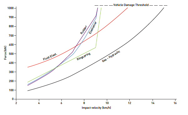
The diagram above shows typical impact forces against impact velocity for the various types of buffer. You will see that the Oleo gas hydraulic buffer gives the lowest force over the velocity range.
Applied impact case used for analysis above.
NON RECOVERABLE TECHNOLOGY
In addition to the various recoverable technologies there are a number of non-recoverable technologies which can be used in conjunction with recoverable units in case of an over speed or crash condition.
Recoverable energy absorption methods commonly used in the rail industry are:
a) Deforming tubes
b) Crush boxes
c) Peeling technology
d) Splitting technology
Oleo's preferred solution is deforming tubes since they yield regular near constant force displacement characteristics and do not require a separate shear out to prevent premature activation. They can also be used in conjunction with Oleo hydraulic capsules and are designed to withstand considerable vertical loads without changing their force deflection characteristics, which makes them suitable for use in the prevention of overriding.
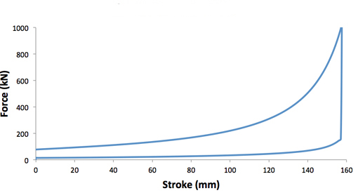
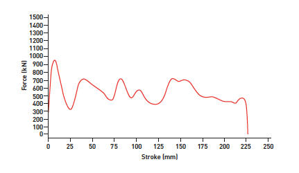
Deforming tubes: The basic principle of operation is to dissipate energy through the extrusion of cylindrical tubes. The tubes can be extruded either though external dies to reduce the tubes diameter or through internal dies to increase the diameter of the tube. The force required to deform the tube will depend on the wall thickness and the material of the tube. A typical dynamic force displacement diagram is given below.
REPRESENTATIVE DYNAMIC CHARACTERISTIC FOR DEFORMING TUBE
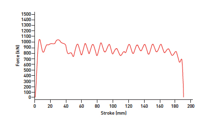
Crush box: The basic principle of a crush box is to dissipate energy through the buckling of a 'box' like structure usually constructed from sheet metal. The main advantage of this type of energy absorber is that it can deform a significant proportion of its original length allowing large deflections. The main disadvantage is that the dynamic force displacement characteristic is highly irregular and the deformation changes significantly if subject to vertical loads.
DYNAMIC CHARACTERISTICS – CRUSH BOX
Peeling technology: The basic principle of operation is to remove metal by peeling or machining the outer surface of a metal tube. The main advantage of this type of device is that, like deforming tubes, it can be designed to take significant vertical loads without affecting its force deflection characteristics. The main disadvantage of this type of device is the need to have a shear out device to prevent premature triggering and the irregular nature of the dynamic force displacement characteristics.
DYNAMIC CHARACTERISTICS – PEELING
Splitting technology: Splitting technology comes in several different forms; the general principle is to absorb energy by splitting a tube lengthwise and plastically deforming the material. The main types either rely on ductile tearing of the material or splitting the material with a wedge. The main advantage of these devices is that they can be designed to give relatively large deflection for a given installation length. The main disadvantage is that they often need a significant force to initiate the tearing or require a shear out device to prevent premature triggering, when used in conjunction with a wedge. They also tend to have an irregular force displacement characteristic and require a space for the material to expand into once the splitting begins.