Leading the world in
energy absorption
Elevator buffers are safety devices which are required to be mounted at the base of an elevator shaft. As with any safety device elevator buffers have to meet with a variety of specifications but probably the most important of these is the manner in which the buffers must bring an impacting elevator car to rest. There are different technical specifications for elevator buffers in different regions worldwide however all employ the same basic performance criteria.
Since the very early days of elevators, a variety of safety systems have been employed to ensure that the elevator will not free fall. The purpose of elevator buffers is to provide protection against the malfunction of an elevator control system resulting in the elevator continuing to travel past the lowest stop to the base of the elevator shaft. The buffers are specified in accordance with the operating velocity and mass of the elevator.
Although freefall is not a realistic event for an elevator, the specification and code requirements are based on the assumption of freefall.
The requirement for elevator buffers fall into two categories depending on the type of buffer.
1. Energy accumulation buffers: These can take the form of simple mechanical springs or polymer buffers which store the absorbed energy of the impact in the form of strain energy. In some accumulation buffers this stored energy can be dissipated on the return movement of the buffer leading to two separate requirements:
a) Buffers with linear and non linear characteristics – these can be used if the elevator does not exceed 1.0m/s
b) Buffers with buffered return movement – these can be used for elevators that do not exceed 1.6m/s.
2. Energy dissipation buffers: These are usually hydraulic buffers which dissipate the energy of the impact in the form of heat during the travel of the buffer. This type of buffer can be used for all rated speeds, but must be used for speeds of 1.6m/s or over.
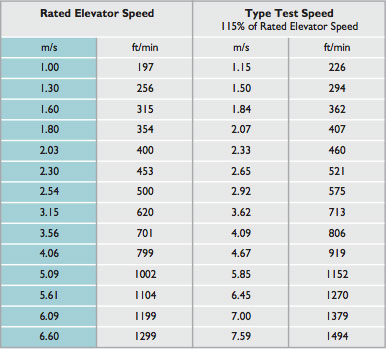
Performance criteria in all specifications is governed by 2 underlying rules which state that the buffer must arrest a freefalling mass traveling at 115% of the rated speed of the elevator:
(i) With an average deceleration not exceeding 1g.
(ii) Without exceeding a deceleration of 2.5g for a time period greater than 0.04 seconds.
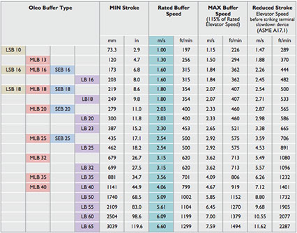
In addition a further, but separate requirement, states that the buffer stroke must be at least as great as freefall distance required to reach 115% of the rated elevator velocity. It is this requirement that dictates the stroke and consequently the installation height of elevator buffers. Due to customer demands, most elevator buffers do not deviate far from the minimum stroke requirement.

The design engineer must consider the stroke requirements in the overall height of the buffer. If telescopic solutions are not to be used then the overall height must be at least double the minimum stroke with a further height requirement to restrict lateral movement when the buffer is fully extended.
Lateral movement should be restricted to +/- 5mm per meter of stroke from the center.
The function of an emergency terminal speed limiting device is to automatically reduce the speed of a car or counterweight by removing power from the driving machine. The device effectively slows the car or counterweight to the rated speed of the buffer before impact. This device would normally be independent of the normal terminal slowdown devices. This is important when selecting a buffer for a particular application. If the emergency terminal speed limiting device is part of the installation then the 'reduced stroke' rules can apply. This effectively reduces the size of buffer required for a particular application.
The calculation for reduced stroke is based on the stroke of the buffer and not the speed of the elevator. The reduced stoke calculation differs in some countries but the basic rules are as follows;
The stroke must not be less than:
a) One half (50%) of the stroke for elevators that do not exceed 4.0m/s
b) One third (33.3%) of the stroke for elevators where the speed exceeds 4.0m/s.
Minimum strokes also apply under some code requirements including EN81.1. Under EN81.1 the minimum stroke should be 420mm for 50% calculation and 540mm for the 33.3% calculation. This does not apply under all code requirements.
Using the reduced stroke calculation a buffer rated at 5.09m/s (1002ft/min) could be used on an installation of 8.8m/s if used with a terminal speed limiting device.
The minimum stroke for an elevator buffer is specified (within EN81.1 and ASME A17.1), as the necessary distance to bring an impacting mass, traveling at 115% of the buffers rated speed, to rest with a uniform deceleration of 1g. However, this is only true if the buffer exerts a constant retardation force over its entire stroke.
A hydraulic buffer can be designed to closely match this idealised performance. This is achieved by precise control of hydraulic oil flow across an orifice throughout the buffer stroke. However, this can only be achieved for one specific impact mass. The same performance is not achievable for the range of elevator masses that are encountered in the real world where the elevator car mass varies with passenger load.
In the elevator application, where there is a need to protect passenger safety, it is important to try to minimise the deceleration experienced during stopping. This can be easily resolved when the elevator is fully loaded but at low loads the same retardation force will slow the elevator more quickly and therefore initially result in higher deceleration for the passenger.
The graphs below compare test data from two hydraulic buffers that both meet the elevator code specification requirement being used to stop an elevator car traveling at 3m/s. This shows the g force that will be experienced by passengers traveling in fully and lightly loaded conditions.
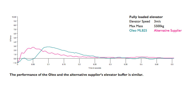
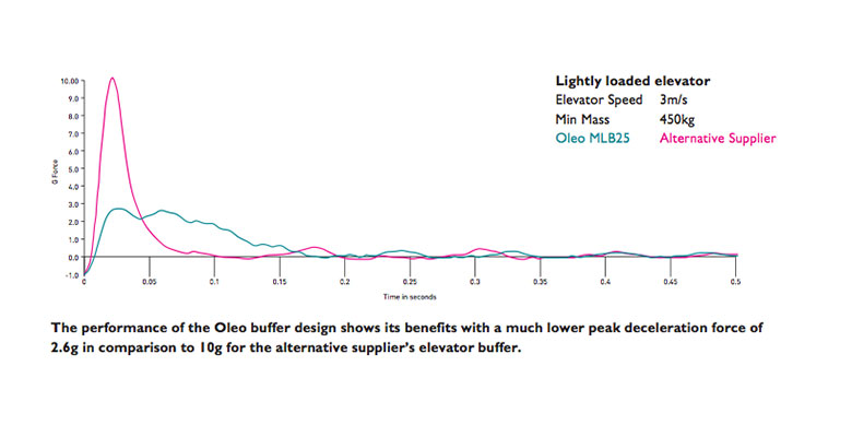
In both load conditions both buffers keep the average deceleration below 1g and do not allow 2.5g for more than 40 milliseconds and therefore are both fully compliant with elevator code specification requirements.
The limiting of peak deceleration force is not required by any elevator code or industry specification. Alternative buffers achieve the average 1g criterion by an initial period of high deceleration followed by extending the final stages as the elevator is coming to rest. The other key elevator buffer specification requires that passengers do not experience more than 2.5g for more than 40 milliseconds but within this period g forces are not limited. However, as illustrated above, in certain conditions very high instantaneous g forces occur and this may cause passenger discomfort.
Oleo has an overall passenger safety aware approach and seeks to avoid the passenger discomfort that may arise from instantaneous deceleration that may even exceed 10g in some circumstances. Many years of in house testing and the development of mathematical algorithms that accurately simulate the performance of hydraulic buffers enable Oleo unsurpassed force control. The design philosophy is to minimise g force for all passenger load conditions the benefits are highlighted in the test data shown above.
Oleo elevator buffers are designed to withstand many more maximum load impacts than elevators are likely to experience in their service life. Despite this, elevator buffers remain an emergency only device. It is never a desirable outcome in the real world to have to rely on buffers to bring your elevator to a stop – that said, it is absolutely essential that you can rely on the buffers in the event that they are required.
It is for this reason that many elevator buffers are fitted with a switch. The switch is positioned to detect that the buffer is fully extended and therefore ready for impact in the case of an emergency. If for any reason the switch does not detect full buffer extension, the entire elevator system is shut down.
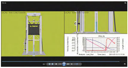
Oleo employs computer modelling and analysis to refine elevator buffers performance. Simulations are compared directly with test results obtained on Oleo's own in house dynamic test facility. The ability to both simulate and test, has allowed increased optimisation of elevator buffer performance, providing benefits in terms of cost, safety and reliability.
Elevator buffers are subjected to a type test before they can be sold to the market. Type test requirements vary depending on country but most follow the guidelines of the European specification EN81.1 or ASME A17.1.
To comply with the requirements of EN81.1 the buffer must perform to the criteria detailed earlier. To establish this, the buffers are subject to drop tests. This is where a mass is dropped in freefall. The drop tests must take place at a temperature between 0°C and 25°C. Tests are conducted with masses at either extreme of the stated mass range of the buffer. Subsequent to the maximum mass drop, the mass must remain on the buffer for a minimum of 5 minutes, after which the buffer must fully re-extend within a time period of 90 seconds. Measurements must be made of the displacement, velocity and acceleration of the freefalling masses at a sample rate of at least 100Hz.
In order to eliminate erroneous noise and high frequency vibration from accelerometer traces, low pass filtering is usually applied to a signal sampled at a higher than required sampling frequency.